Technical Information
If you're looking for some technical nitty-gritty of Synthesizers.com systems, you've come to the right place.
The information here is for reference only. We do not offer advice about DIY projects. We do not recommend DIY of power system components due to the obvious dangers involved. Products damaged by modification or connection to DIY power supplies or other DIY components are not covered under warranty.
Design Philosophy
- All analog circuitry for signal processing.
- Voltage levels compatible with most other modular systems.
- Control ranges go beyond useful limits, even if clipping may occur.
We let you decide what the limits are. - Waveforms and responses are not made unnaturally perfect,
in order to produce that traditional analog sound. - Jacks located on the panel to promote intuitive usage, not to reduce
cable clutter which occurs anyway on multi-row systems. - Separate functions are put on separate modules, not combined.
- All ICs are socketed for easy repair.
- We don't rely on the panels to carry ground.
- Separate 5 volt power supply for digital and LEDs.
- Precision voltage references used where pitch can be affected.
- Circuit boards are mounted parallel to panel to reduce cabinet depth.
- Truly modular design, even power modules, cabinetry and controllers.
- Attenuators on inputs where it makes sense, to ease patching.
- Consistent panel layout - text and jack/pot placement.
- Sliders are not easy to adjust, we prefer knobs.
- Big knobs, 1/4 jacks, but resist over-populated panels.
- Panel sizes compatible with Moog modular.
Electrical Specifications
We use voltage levels that are common to other analog synthesizers for easy interfacing.
Pitch Control Voltages: 1 volt per octaveWaveform Voltages: 10V peak-peak
Gates: 0-5V positive ON, threshold 1.5V (Learn about gates)
Signal Input Impedance: 100K
Signal Output Impedance: 1K
Envelope Voltages: 0-5V
DC Power: +15V, -15V, +5V
AC Power: 110VAC, 220VAC
Panels
Synthesizers.com Q series modules adhere to the MU (Moog Unit) format modeled after the Moog Modular.
Each synthesizer module consists of a front panel and a circuit board mounted on the back parallel with the front. Modules may be removed from the synthesizer cabinet after removing the mounting screws and the power connector. Some modules are attached to another module behind the panel as is the case of Aid modules.
Panels are made of .062" aluminium, sanded, formed on the sides for strength, masked, painted, textured, then silkscreen printed. All panels are 8.75" in height and come in various 'widths'.
Panel Widths
A single width panel is 2.125" - all others are multiples of this single width. Common sizes are single, double, quad, and octal, but any multiple of a single will fit in our cabinetry.
Double: 4.25"
Quad: 8.5"
Octal: 17"
CAD drawing of a panel.
Mounting Flanges
Mounting flanges at the top and bottom of each module panel are .4" tall which mates nicely with a 3/8" (.375) mounting surface.
Mounting Hardware
We use #6 x 1/2" black wood screws to mount modules to wooden walnut studio cabinets and portable wood cabinets. We use #6-32 x 1/2" black machine screws to mount modules to rack frames and Box cabinets. See our Parts page for these screws.


Panel Graphics
Panel graphics are UV-printed using white ink.
Font for Module Part Number: Arial 10pt all-caps
Font for Module Title: Arial Bold 12pt All-caps
Font for Control and Jack Titles: Arial 10pt All-caps
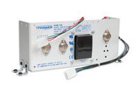
Power Supplies
We use linear power supplies to reduce noise. They're heavier and more expensive than switching power supplies. These supplies deliver +15V, -15V, and +5V for use by the modules in your system. A power supply has 2 cables: 1 for the AC power input which connects to a Q102 or Q137 power module, and 1 for the DC power output which connects to the cabinet's wiring harness.
See the Power products page for all the details.

Signals - 1/4" Phone Jacks
Our modules use standard 1/4" jacks and plugs for all waveform and control voltage routing. These are much easier to handle and more durable than 3.5mm connectors, and offer a shielded ground unlike banana connectors. 1/4" jacks and plugs are also used on most other audio equipment allowing easy interfacing.
Use the Q120 Connector Interface Module to interface system signals to RCA connectors, 3.5mm connectors, and banana connectors. Also see the Q121 Banana Jack Interface Module, and the Q122 Mini-Jack Interface Module.

External DC Power - 6 pin DIN
We use 6 pin circular DIN connectors to supply DC power to the external world using QIC cables. QIC cables carry power to other cabinets and to controllers. This DC power connector can be found on the Q103 DC Power Interface Module, the Q137 Power Module, Box cabinets, and controllers.


AC Power - IEC
We use standard IEC connectors for AC power. This allows use of your synthesizer in almost any country when using the correct power cord.
Some of our power systems are universal input and some require changing a switch to select the input voltage.
See the Power products page for all the details.
Internal DC Module Power - 6 pin MTA
We use MTA .1 connectors for DC power supply connections to modules. This has become the industry standard for modern MU (Moog Unit) format modules - sometimes called the "DotCom power connector". Modules have the male PCB mount version, and the cabinet's QDH cable harness has the female version.

Pin #2 is removed from male connectors, and pin #2 is plugged on female connector to act as a KEY so the connector can not be plugged in backwards or shifted.
Female 24AWG cable mount: AMP #6404416
Male PCB mount: AMP #6404566

Connectors, Buttons, LEDS - 2 pin MTA
We use 2 pin .1 MTA connectors for jacks, push buttons, LEDs and other devices requiring only 2 pins. This makes repairs and maintenance very easy without needing to solder.
Female cable mount: AMP #6404412
Male PCB mount: AMP #6404562
2 = Ground (ring)
Internal Pot/Switch - 3 pin MTA
We use 3 pin .1 MTA connectors for potentiometers, SPDT switches and other devices requiring 3 pins. DPDT switches have 2 of these connectors. Replacement is easy and doesn't require soldering.
Female cable mount: AMP #6404413
Male PCB mount: AMP #6404563
2 = Wiper
3 = CW Side